1
2

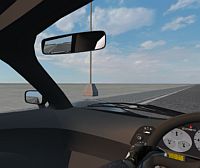
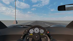
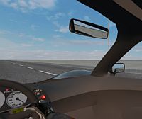
Mirrors special placement problem  Car has two internal mirrors and two external mirrors: four mirrors total, but LFS support only three: two external and one internal, which have to be centered.
Using two separate "internal mirror" subobjects, mapped with different cutouts (doesn't matter cutout flipped or not) — mappings rotated along Z together with last subobject towards "eyes".
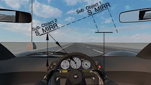
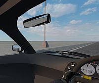
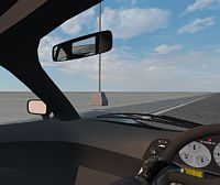
After removing left "internal mirror" subobject, mapping rotated, same as before, but in the opposite direction.
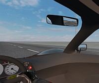
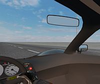
Using united "internal mirror" subobject (doesn't matter build mirrored or not, or using flipped opposite side cutout or not).
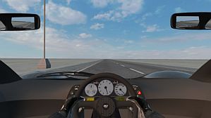
Changing internal mirrors subobject to "attachment" (two external mirrors already mapped) leads to all mirrors turn black (doesn't matter build mirrored or not, or using flipped opposite side cutout or not).
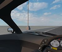
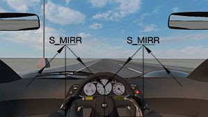
After removing mappings from external mirrors, internal works like this:
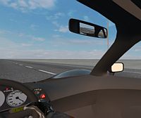
Сonsidering central seating position, default POV=90deg, vehicle width, looking straight you can't see external mirrors, it makes sense to stick with last scheme for a while.
Car has two internal mirrors and two external mirrors: four mirrors total, but LFS support only three: two external and one internal, which have to be centered.Using two separate "internal mirror" subobjects, mapped with different cutouts (doesn't matter cutout flipped or not) — mappings rotated along Z together with last subobject towards "eyes".
After removing left "internal mirror" subobject, mapping rotated, same as before, but in the opposite direction.
Using united "internal mirror" subobject (doesn't matter build mirrored or not, or using flipped opposite side cutout or not).
Changing internal mirrors subobject to "attachment" (two external mirrors already mapped) leads to all mirrors turn black (doesn't matter build mirrored or not, or using flipped opposite side cutout or not).
After removing mappings from external mirrors, internal works like this:
Сonsidering central seating position, default POV=90deg, vehicle width, looking straight you can't see external mirrors, it makes sense to stick with last scheme for a while.
Last edited by Egor K, .
Reason : couple minor fixes
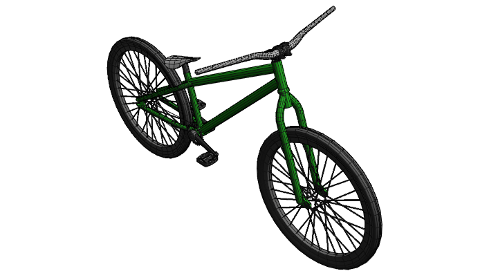
Street MTB
I use to have agang exe 24 (2011) street MTB and want recreate it inside LFS.
Who knows maybe LFS someday will support bunnyhop or at least hop (like GTA:SA does
 ).
).
Crank arm length = 0.175m
Rider mass = 70kg
Hand power (pulling handlebar) = 30kg
therefore
Rider force on pedal = (70+30)kg*9.8=980N
Engine moment = 980N*0.175m=171.5N*m
Since model mass (with rider) exceeds actual mass (due to: motor 26 kg, battery 7kg, wheels 19kg) I decided to set 152% torque.
IRL 12.3kg bike plus 70kg rider = 82.3kg
LFS 55.0kg bike plus 70kg rider = 125.0kg (152%)
At first I thought to do it quickly, but got a little bogged down in the details
Who knows maybe LFS someday will support bunnyhop
or at least hop (like GTA:SA does).EngineI figured that way:
Crank arm length = 0.175m
Rider mass = 70kg
Hand power (pulling handlebar) = 30kg
therefore
Rider force on pedal = (70+30)kg*9.8=980N
Engine moment = 980N*0.175m=171.5N*m
Since model mass (with rider) exceeds actual mass (due to: motor 26 kg, battery 7kg, wheels 19kg) I decided to set 152% torque.
IRL 12.3kg bike plus 70kg rider = 82.3kg
LFS 55.0kg bike plus 70kg rider = 125.0kg (152%)
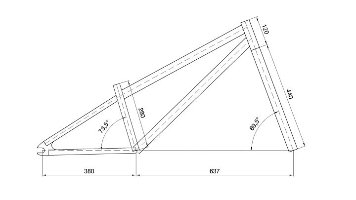
Final DriveBike has 25 tooth front and 11 tooth rear sprocket, so 0.44 gear ratio. Since LFS allows 0.50 minimum, compensate with final drive ratio of 0.88.
DimensionsAccording to dimensions from agang 2011 catalog (46.2 MB) (page 63/80):
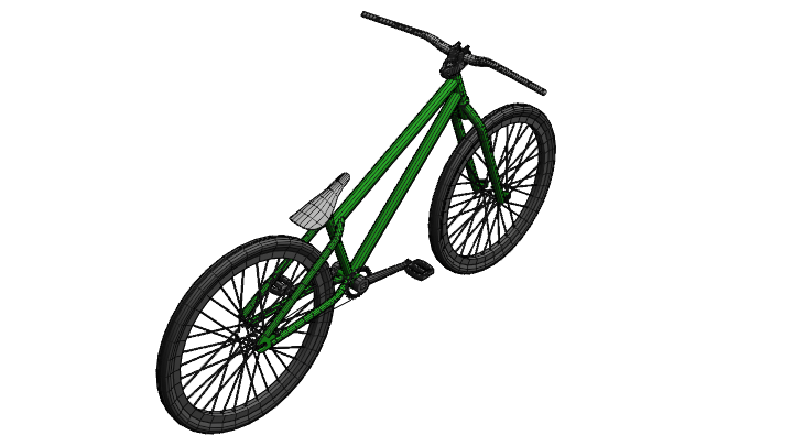
MeshCurrent progress:
At first I thought to do it quickly, but got a little bogged down in the details
Thank you!
1 Load *.obj with lod2 (it will replace everything and became main object)
2 Save that main object from Modeller (mesh editor)
3 Load whole Vehicle again
4 Place triangles from main object to any other than first layer (must be empty)
5 Add "new subobject"
6 Load saved subobject from (2) by subobject > load
7 "merge into main"
8 Go to main object and select all triangles from first layer (that's why in (4) you need clean first layer - former subobject moved to it and now it's easy to select only lod2 triangles)
9 "add to : lod2"
10 remove lod2 tris from lod1
No matter which lod I choose, Modeller always shows all the points. Thus, regardless of the active lod "A: all" selects literally everything 
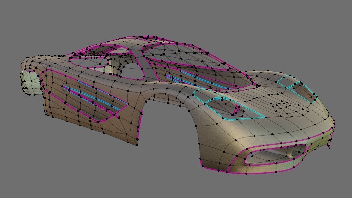
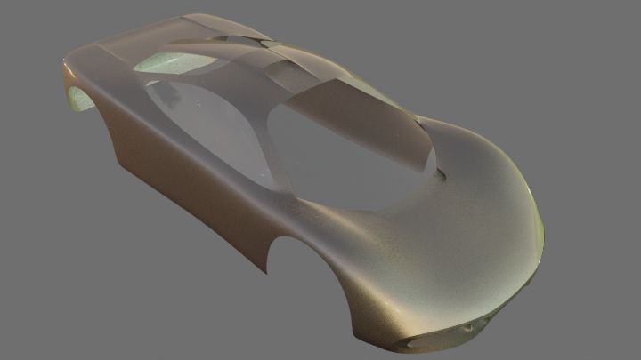
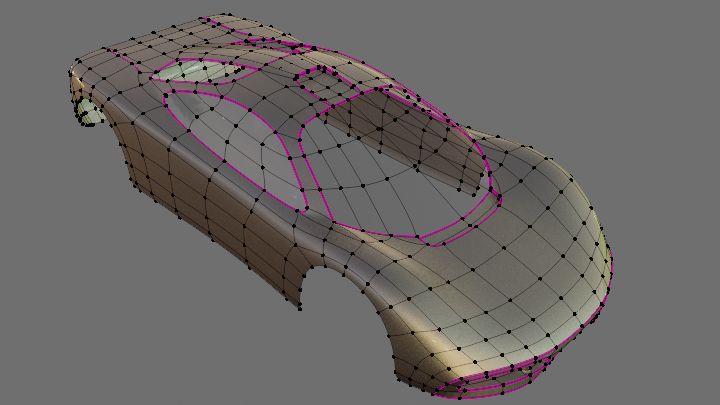
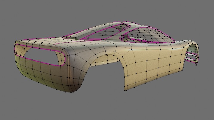
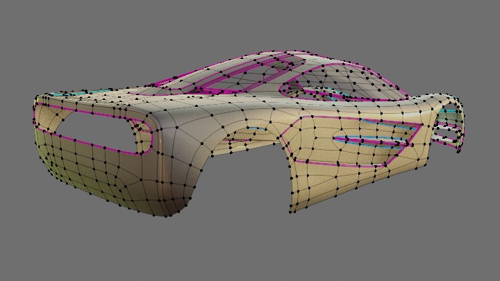
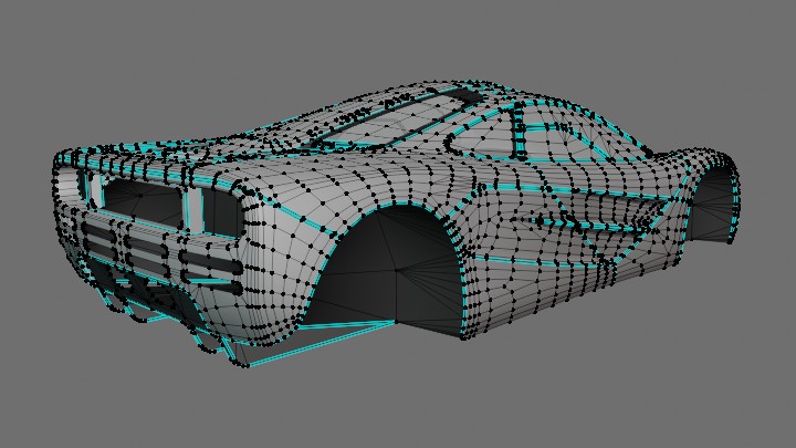
A couple of workflow tricks.
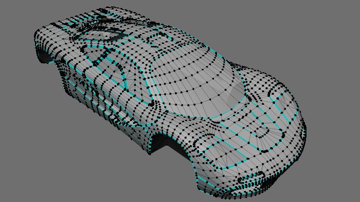
While working on external shape to see clearly how adjust shape put marks, such as windows, doors, headlights, etc. by projecting NURBS curves:
Later, these contours were used to build the final mesh:
1 draw nurbs curve
2 add Shrinkwrap modifier (wrap method: Project, select Axis, allow Negative direction as curve is outside)
3 choose curve resolution (object data properties > Resolution Preview)
4 convert curve to mesh (check keep original)
5 join (Ctlr+J) converted curve to the final mesh
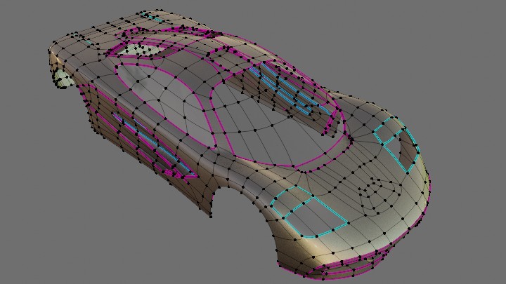
Since back of air duct meant to fit smoothly into external shape, I applied Lattice modifier to its part.
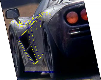
Image source: https://cars.mclaren.com/us-en/legacy/mclaren-f1
While working on external shape to see clearly how adjust shape put marks, such as windows, doors, headlights, etc. by projecting NURBS curves:
Later, these contours were used to build the final mesh:
1 draw nurbs curve
2 add Shrinkwrap modifier (wrap method: Project, select Axis, allow Negative direction as curve is outside)
3 choose curve resolution (object data properties > Resolution Preview)
4 convert curve to mesh (check keep original)
5 join (Ctlr+J) converted curve to the final mesh
Since back of air duct meant to fit smoothly into external shape, I applied Lattice modifier to its part.
Image source: https://cars.mclaren.com/us-en/legacy/mclaren-f1
Triangle mode shows tris only from selected lod. But point mode shows vertices from all three lods.
This not only confuses work, also changing one lod leads to changing another, for example: duplicate triangles from lod2 to lod3 > using "fuse to green" to reduce lod3 tris = points from lod3 and lod2 fused synchronously. How to make visible and selectable points only from current lod?
This not only confuses work, also changing one lod leads to changing another, for example: duplicate triangles from lod2 to lod3 > using "fuse to green" to reduce lod3 tris = points from lod3 and lod2 fused synchronously. How to make visible and selectable points only from current lod?
SOLVED by Flame CZE
Last edited by Egor K, .
Reason : Problem solved
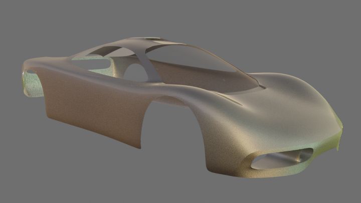
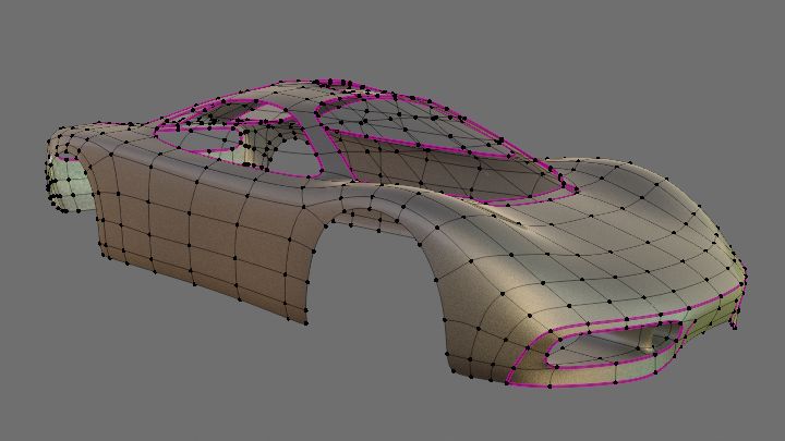
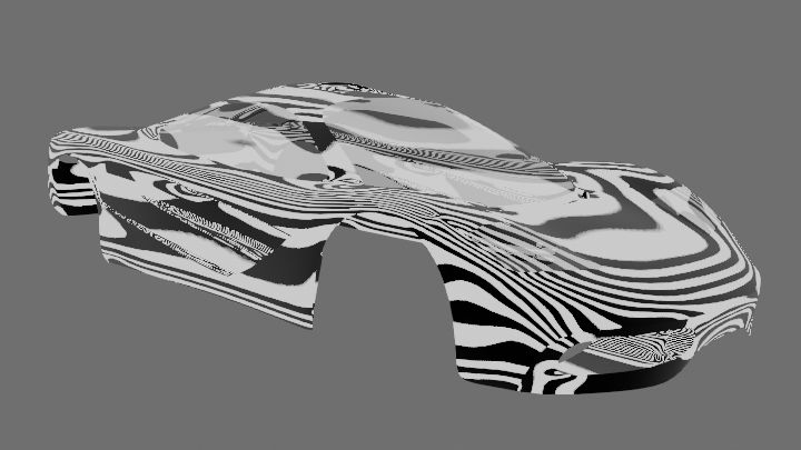
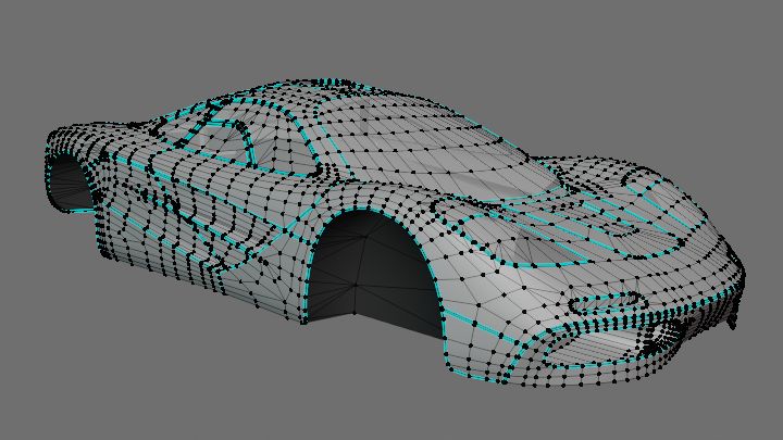
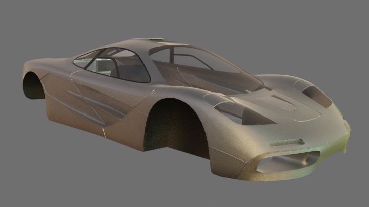
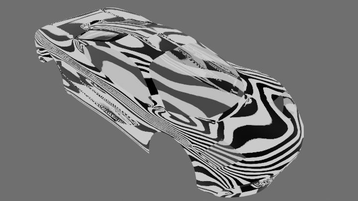
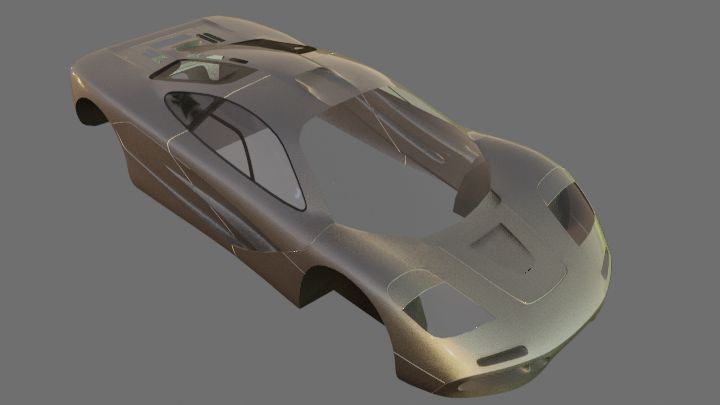
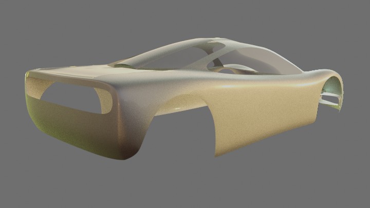
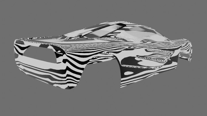
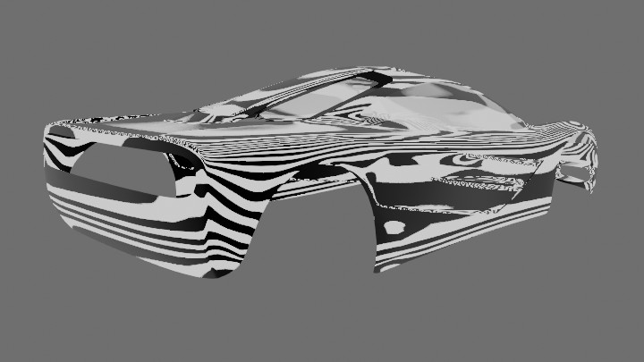
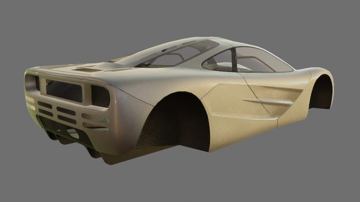
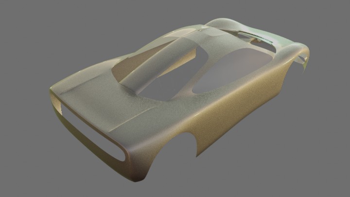
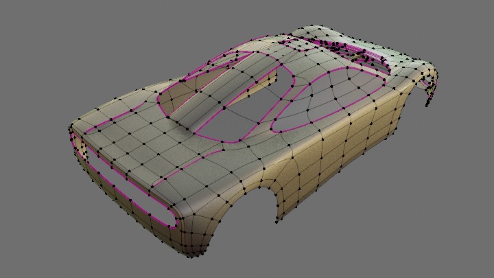
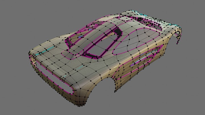
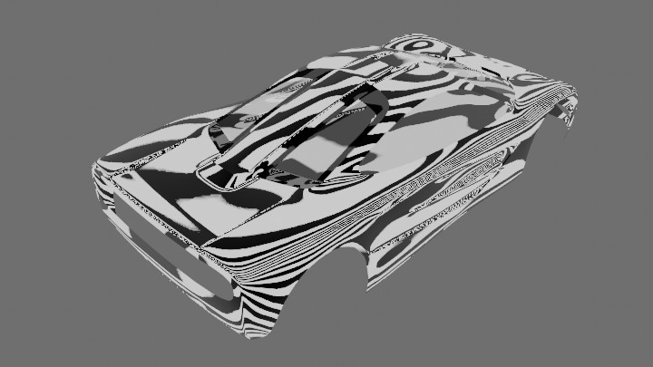
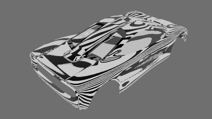
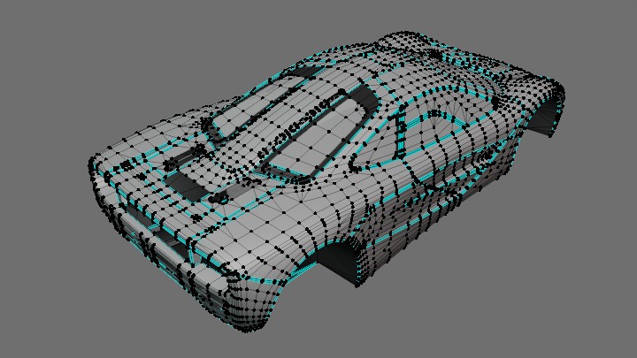
Thank you guys! Some progress in the following sequence:
1 external shape
2 external shape mesh + SubD
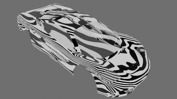
3 semifinal mesh + Subd
4 check
5 after shrinkwrap (3) to mesh (1)
6 final mesh
7 final


1 external shape
2 external shape mesh + SubD
3 semifinal mesh + Subd
4 check
5 after shrinkwrap (3) to mesh (1)
6 final mesh
7 final
Last edited by Egor K, .
Reason : rearranged images
If you agree with everything that weisenheimer said while the shape of a car is obviously copyrighted, how can precise recreation of a real model be legal at all without permission from the copyright holder even if car named different, but you can instantly recognize what car it really is?
Second screenshot from Fairfield Test Centre pack shows a straight of regular artificial bumps, it would be cool to have also random ones, like Belgian Pavé
Yes!
I could not even dream of such a program in the foreseeable future. It is a pity that mainly big V8 engine is demonstrated and the 747cc motor is a bit more bass than you'd expect.
It is similar ONLY way it looks! It contains default frame (center of gravity and moment of inertia not relevant, at all), engine and fuel tank coordinates = 0,0,0 and so on we have Ambulance Truck lighter than Miata with kart-grade handling. I do not wish Mr. Dygear judge the accuracy of LFS mods by hususu9633 made mods.
As I see workflow:
1 make shape (no mouldings and gaps)
2 make sure general shape is ok
3 apply subdivision
4 make gaps and mouldings by offset edge slide
Gaps and mouldings in low-poly mesh are:
5 hindrance to shape correction
6 enemy of smooth shape transition (not visible on your screenshots because there is no matcap)
Am I wrong?
Ultimate Road Car
MassAccording to book "Driving Ambition" kerb weight (incl half tank): 1138kg. Distribution front/rear: 41.2/58.8%.
EngineAccording to audiosignal.co.uk engine+all ancillaries, the exhaust and silencer is 266kg. Engine mass 303kg automatically determined by Vehicle Editor a bit heavy though.
Plate claims idle 900 rpm and another engine settings, most of all I like ignition timing string. Whole video by James Cottingham (DK Engineering TV) worth watching.
Steering
- Maximum Lock — I figured maximum lock is 33 degrees while testing on Layout Square — according to Autocar magazine turning circle is 13 m.
- Steering Wheel Turn (ONE WAY) 504 degrees — according to Autocar magazine lock to lock 2.8 turns.
- Parallel steer — quote from C466/007/93 (Concept and design of the McLaren F1 suspension systems), see attachments to post by user flemke on 26-09-2019 (hereinafter the "C466/007/93"): "...around 40% of full ackerman was adopted for F1."
Suspension
- Camber — planned: 45' F&R, but user tortoise claimed: 1.75 F; 0.75 R.
- Inclination. Front — according to audiosignal.co.uk — 8 degrees. Rear I tentatively figured by freeze frame tracking. Whole video by Tim McNair (Grand Prix Concours) worth watching.
- Caster — according to audiosignal.co.uk — 4.6 degrees (46 is written — I think point just lost).
- Scrub radius — according to audiosignal.co.uk is 25 mm.
- No rear anti-roll bar. Here's what Gordon Murray said about the anti-roll bar at the front only (interview with Henry Catchpole on Carfection YouTube channel):
- Roll centre — according to C466/007/93: 3.1 Roll centre "...the centres be placed at 30mm and 60mm above the ground, front and rear respectively."
- Roll compensation — planned 75% roll compensation (4.4 degrees for 80 mm travel). Later in C466/007/93: "...55-65% roll compensation...". So let's set it to about 3.7 degrees for 80mm travel.
- Motion Range — according to audiosignal.co.uk: 170mm (90 bump + 80 rebound).
- Ground clearance — 120mm.
No anti-dive confirmed.
I like road car behavior with noticeable suspension travel, that real feel no other sim but LFS simulates so well.
Final driveLock is 40% — according to netcarshow.com.
Maximum speed with claimed gearbox ratios from Autocar magazine allegedly doesn't match well-known record 386.7 kph as redline was raised for record run, detailed information on Racing Line magazine.
TyresTyre pressure information.
AerodynamicsMaybe the coolest thing about this car, described by Gordon Murray (on Speedvision channel):
Production cars don't have front fog lights as early prototypes.
MeshMainly using this main reference sketch, which has accurate object positions.
Some progress (GIF)
Sizes correspond to manual.
Rims modelled by converting NURBS spoke profile to mesh with shrinkwrap modifier.
Rear lights: red COBO 02.279, amber COBO 02.282.
Article in Racecar Engineering (June 1996) has very detailed monocoque description, including center beams dimensions: height 250mm (match main reference sketch) and width 150mm on floor, as well as distance between them — 22 inches.
Vehicle Editor does not allow place two kinda-rear passengers due well-known unique three-seat layout.
Steering wheel was modelled using pic from book "Driving Ambition" which I redrawn to better mesh align.
Clocks
Interesting statement about about the first implemented feature:
Thanks to Jay Leno we can see McLaren F1 fuel cell and know it must be replaced proximly every five years (same tells whichcar.com.au).
People working on IRLBarry Lett had arrived from Lotus to oversee body engineering.
Paul Martin was in charge of composites.
Steve Randle did stress analysis and ended up working on the car’s suspension.
(source)
Peter Stevens — stylist
Last edited by Egor K, .
Reason : add some info (engine and suspension, also quotes), add ARB info, deleted Bellm's complaint — it concerns GTR, added quote about rear ARB, 241016:removed questions, will ask in the Assistance topic
A good idea.
It would also be very useful to see in real time: coordinates of roll center and its offset from COG.
Trying to understand units of measure in dashboard texture.
It's 512*512px centered, and X and Y coordinates of speedo and tacho are unitless fractions of half (256px) of texture (see attachment).
One unit of dimension of multi function display is 1/64 of whole texture width 512/64=8px
But radius of speedo and tacho does not correspond to fractions nor pixels.
I vote for it, even regular everyday normal e34 has caster almost of 8 degrees

Snoop serious as always!
I like the fact that stock version comes first. Despite stock wheels sinking in arches (which is real).
I like the fact that stock version comes first. Despite stock wheels sinking in arches (which is real).
Custom access
Trying to understand why there is custom access to mods since there is no way to monetize?
I don't complain about custom access at all. Of course, the right of the author to decide who to give access to the mod. Sometimes I ask author online for access, but quite often they ignore it — can't blame them, cause what's the point of custom access when you're ready to give access to random dude online?
But why do I even see here on the forum when it's private? It makes it some kind half-private: see, but don't touch?
Also, why is custom access mods moderation is public?
Isn't this one of the reasons for delay of "public mods" reviews?
How about at least making viewing public mods a priority over custom access mods? Or even make it true private.
Is it possible to set distance of spokes from edge of rim (or from center) separately for front and rear?
When editing either rim or spokes, I did not find buttons to switch axis.
When editing either rim or spokes, I did not find buttons to switch axis.
1
2
FGED GREDG RDFGDR GSFDG